
Chaff Cutter 3D Model
Chaff is hay cut into small pieces for feeding to livestock (Mohan D and Kumar A, 2004); it is a good fodder, and at its best is cleanly and evenly cut, free of dust, of good colour and with a fresh aroma. Chaff can be purchased from commercial chaff cutting mills.Cutting chaff can be done by manually operated machine and electric operated one, As far as cutting by manually operated machine is concerned. Traditionally for the operator it is done manually which is physically demanding through it energy and postural requirements and is commonly regarded as source of drudgery, many farmers associated with this task reported back, shoulder and wrist discomfort. It may also cause clinical or anatomical disorders and may affect worker's health.
Types of chaff cutter:
1. Chute-Fed Chaff Cutter - A chaff cutter in which the feeding of the fodder crop is done through a chute.
2. Conveyor Fed Chaff Cutter - A chaff cutter in which the feeding of the fodder crop is done through a conveyor.
3. Let-Fall Type - A chaff cutter in which the cut fodder is dropped down to the bottom of the chaff cutter.
4. Throw Away Type - A chaff cutter in which the cut fodder is thrown away to the front ward of the chaff cutter.
5. Blow-Up Type - A chaff cutter in which the cut fodder is blown up through the blow-up pipe.
6. Fly Wheel Type - A chaff cutter havi.ng rotating fly wheel with blades.
7. Cylinder Type - A chaff cutter the cutting mechanism which consists of a rotating cutting cylinder.
Types on the basis of cutting mechanism:
a) Fly wheel type, and b) CyIinder type.
On the basis of cut-chaff dropping position, the chaff cutter shall be of following types:
a) Let-fall type, b) Throw-away type, and c) Blow-up type.
On the basis of feeding system, the chaff cutter shall be of following types:
a) Chute-fed and b) Conveyor-fed.

Chaff Cutter 3D Model With 1 HP Electric Motor.

Chaff Cutter 3D Model With 3 HP motor
Components of Chaff Cutter:
1. Flywheel
The flywheel is made of cast iron or Steel For mounting blades and storing energy for cutting the chaff during operation. The flywheel should be heavy and balanced for cutting of chaff with efficiency. A flywheel of 900 mm to 1350 mm diameter shall be provided. The flywheel shall have two arms. Each arm shall be provided with one square hole for fixing the handle; three holes for fixing the blade and six tapped holes for fixing the bolts for blade setting adjustment. At the centre of the flywheel, a circular hole shall be provided for connecting it to the main shaft. A hole of 10 mm diameter shall be made in the rim of the flywheel parallel to the direction of the hub hole. The weight of the flywheel shall not be less than 24 kg.
Chaff cutter shall be provided with a linchpin with the chain to lock the chaff cutter flywheel when it is not required to be operated. This shall be fixed on the flywheel main gear shaft at the end so as to restrict the movement of the system. This is especially needed to lock the movement of the chaff cutter blades in order to avoid injuries due to accidental rotation when chaff cutter is not in use. The linchpin shall be fastett%dto the body of chaff cutter with the help of the chain. A bolt shall also be fitted in both the holes (hole of leg and hole of flywheel rim) and tightened with a nut.
2. Feed Roller: Feed rollers are provided for dragging crop inside the cutting housing for preventing hazards to the human being. A guard should be provided on the rollers and cutting housing for avoiding accidents during feeding the crop.


1. Stand
|
11. Chain cover
|
2. Hear housing
|
12. Hopper/Chute
|
3. Power source (3 Hp Motor)
|
13. Gear 18 teeth
|
4. Blade
|
14. Transmission system cover
|
5. Flywheel pulley cover
|
15. Roller
|
6. Flywheel pulley
|
16. Motor pulley
|
7. Flywheel cover handle
|
17. Belt
|
8. Flywheel
|
18. Gear, 33 teeth
|
9. Reverse/Forward Lever
|
19. Gear, 49 teeth
|
10. Chain
|
20. Gear, 7 teeth
|

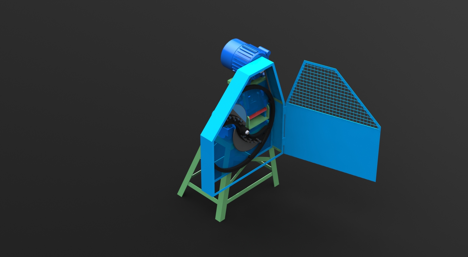
Chaff cutter Vertical Model 3D view

Chaff Cutter Isometric View With All components
3. Feeding Trough :- A rectangular or trapezoidal trough shall be attached on the rear side of the shear plate. The trough shall be detachable Provision for changing the angle of placement of trough shall be provided. At the rear side of the trough a support should be provided. The total length of the trough shall be minimum of 900 mm.
4. Front Safety Guard A front safety guard shall be tightly fitted on each knife blade of the chaff cutter. It shall be made of mild steel rod which shall be given a curvature as of chaff cutter blade and have two holes attwo ends for fitrnent in the chaff cutter with the blade mounting bolts (see Fig. 5). This device stands a little away from the blades and prevents injuries to the limbs as it pushes the limbs away and acts as a warning signal before the blades hit the limb.
5. Cover Plates:- Two sides and one top cover plates shall be provided to protect the feed-rolls as well as for proper mounting of the worm and worm gears. Both the side plates shall be attached to a tie rod. The rod shall be of minimum ’225 mm in length with both the ends threaded. The top cover plate shall have 11 full teeth.
6. Shear Plate:- A rectangular plate with top open, shall be attached at the front of the feed rolls. The width and height of the plate when measured internally shall be minimum 207 mm and 105 mm respectively. The shear plate shall have 12 fill teeth.

Shear Plate
7. Stand :- Stand shall consist of four legs, leg supports and one finger in each leg. The leg shall be made of angle section of minimum 50 mm x 50 mm x 2 mm size. The leg support may be detachable or riveted with the leg. The fingers may be a separate component attached to the leg or maybe made by taking out at the bottom of each leg. The total height, length and width of the stand shall be minimum of 750 mm, 600 mm and 550 mm respectively. In one of the legs a hole of 10 mm shall be provided at a point coinciding with the hole made in the rim of the fly wheel.

8. Worm Gears There shall be two gears; one located at upper side and other at the lower side of the worm. The outer diameter of the gears shall be 125 mm or 133 mm and there shall be 15 teeth in each gear. At the option of the purchaser the gears may have 11 or 13 teeth. The gear shall be attached with axles by hexagonal bolts.

9. Blades:

Can u plz tell me how can we design this
ReplyDeleteCan you send me .dwg of blade.
ReplyDeletePlease
Thanks
Can u send me the 3d drawing of the model. please
ReplyDeletethanks.
Thank you for your post. Can u send me the 3d drawing of the model. please Chaff Cutter Price an insight into this topic.
ReplyDeleteSend me the drwing. Of the head
ReplyDelete